1. Introduction to Rotary Drum Dryer
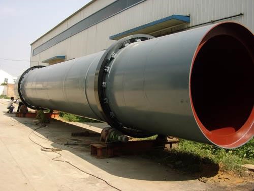
The rotary drum dryer series has such advantages as stable operation, large processing capacity, large operating flexibility, wide adaptability, simple operation, convenient maintenance, long life, low energy consumption and good drying quality. It is widely used in the dehydration of metallurgy, building materials, light industry, chemical industry, fertilizer, feed, mining and other industries.
2. Equipment composition
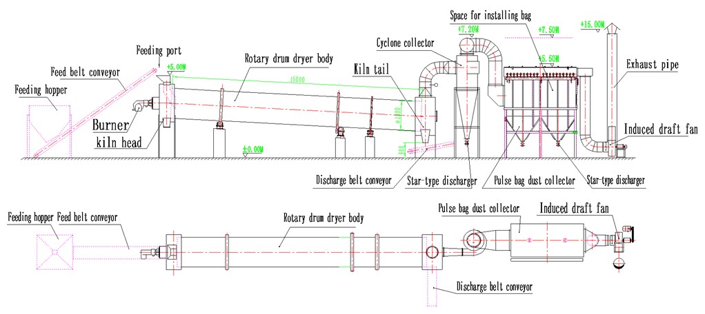
It is mainly composed of blower, heating device, rotary drum body, collector (cyclone collector and bag filter), discharger, air supply pipeline, induced draft fan and electrical control cabinet.
3. Working principle
The blower blows the high-temperature furnace gas or high-temperature flue gas (temperature can be adjusted) generated by the hot air furnace into the drum of the dryer. After the wet material is put into the drum dryer from one end, the material is evenly distributed and dispersed in the dryer under the turning of the uniformly distributed lifting plate in the inner drum and is fully in contact with the parallel (countercurrent) hot air, which accelerates the dehydrating heat transfer and mass transfer. During the dehydrating process, the material can be controlled to move to the other end of the rotary dryer under the action of the inclined drum, lifting plate and hot air flow to complete the drying process. Water vapor and dust-containing gas are filted by the dust collector and discharged into the atmosphere by the exhaust gas pipe system. The dehydrated material is discharged from the tail of the kiln. The extremely small dust is collected by the cyclone and bag dust collector and discharged in a centralized manner. 4. Applicable materials
Ore, blast furnace slag, coal, metal powder, phosphate fertilizer ammonium sulfate, GP foaming agent, wine lees, light calcium carbonate, activated clay, magnetic powder, graphite, Chinese medicine residue, etc. 5. Specification
Type | Cylinder | Evaporation Intensity (KgH20/h.m3) | Capacity | Power | Dimensions(length×width×height)(mm) | ||||
Inner Diameter | Length | Thickness | Inclination | Rotating Speed | |||||
GZT1.0×8 | 1000 | 8000 | 8 | 1~5 | 3~8 | 20 | 6.0 | 5.5 | 9000×2500×3250 |
GZT1.2×10 | 1200 | 10000 | 10 | 20 | 11.3 | 7.5 | 11300×2650×3500 | ||
GZT1.5×12 | 1500 | 12000 | 12 | 20 | 20.0 | 15.0 | 13750×3100×3600 | ||
GZT1.8×14 | 1800 | 14000 | 12 | 20 | 36.0 | 18.5 | 15600×3430×3700 | ||
GZT2.0×18 | 1800 | 18000 | 12 | 20 | 46.0 | 22.0 | 20000×3900×4000 | ||
GZT2.0×20 | 2000 | 18000 | 14 | 20 | 56.0 | 22.0 | 20000×4200×4450 | ||
GZT2.2×20 | 2000 | 20000 | 14 | 20 | 61.0 | 22.0 | 22100×4300×4450 | ||
GZT2.4×22 | 2200 | 20000 | 14 | 20 | 75.0 | 30.0 | 21400×4600×4800 | ||
GZT2.8×18 | 2400 | 22000 | 16 | 20 | 97.0 | 37.0 | 23600×4100×4800 | ||
GZT3.4×20 | 2800 | 18000 | 16 | 24 | 110.0 | 75.0 | 20000×4000×5100 | ||
Note: The evaporation intensity varies greatly with the temperature of the hot air. This table calculates the evaporation intensity based on a hot air temperature of 200 degrees Celsius and an exhaust temperature of 80 degrees Celsius.
4. Sketch Map


